Garrattfan's Modelrailroading Pages
AD60
8.1 Preparing for final assembly
| Between painting and final assembly there is a host of chores to be completed. It is easy to become impatient at that stage and rush things to get the project finished, but I have learned by now that is generally not a very good idea. Take your time. | |
 |
First task is assembling the bogies.
Parts laid out |
 |
All covers filed to fit. They do not fit as supplied, so take care to ascertain a good fit before you start swaying with the glue pot!
I glued with strategically placed drops of CA which were drawn into the seams by the capillary action. I am always wary of CA because it gradually becomes brittle, but an axle dropping out can easily be repaired. So okay in this situation.
To protect the axles from being compromised by CA seeping into the axle "bearing" I smeared them with grease. |
 |
Done |
Hmm it is beginning to look like a locomotive |
|
Next thing is to get the bogies fixed, on the previous photo it was just assembled for the show.
|
|
 |
First thing I learned when assembling the rear unit (as on the photo above) is this that the bogie pin on the inner end is a bit short. Turn a nut on until the bolt is flat on its surface and the inner bogie will be lifted off the track. A guarantee for derailments. The bolt has lost its current conducting function because I have made wipers on all eight drivers (see the section on electric pickups). So I removed a few insulating rings which lowered the bolt by about a nut height. Just enough.
|
 |
Now comes the question: how on earth do I get a bogie on a bolt with a coil spring and at the same time move a retaining washer in between. |
 |
The trick is pretty simple. Move the washer over the spring. |
 |
Push it down all the way. Now keep it firmly there. If you release it now you will spend the rest of you valuable hobby time of this day inventing new words while inspecting all nooks and crannies of your hobby room in the quest for the fugitive washer and spring. |
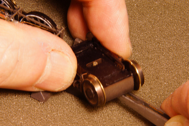 |
Move the bogie over it. The photo is a bit blurry, but remember it is real life action! |
 |
Keep it firmly pressed down and move the tweezers out. |
 |
Secure it with the nut |
 |
Put the chassis on the rails. The force of the coil spring on the bogie will lift the chassis off the rails. Now turn the bolt step by step decreasing the gap between the rails and the wheels until the chassis just tangibly touches down on the rails if you push on it (the gap is about 0.5 mm wide then) Do not worry about the fact that the chassis is lifted off the rails. The weight of the superstructure will later push it down again. The bogie is now sprung a bit and will be able to cope with small unevennesses in the track far better. When happy, secure the nuts of the bogie with a drop of CA. |
Please note that the front bogies hide the bolt that fastens the superstructure to the chassis. The nut of that bogie is best secured after the superstructure has been screwed onto the chassis during final assembly. |
|
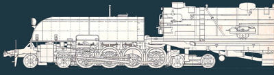
Completed chassis, except for one valve gear set, which is still awaiting new crankpins at this stage. And one motor of course... |
|
| At this stage I dunked both units (less motors and gear boxes) in a commodious bath with a little blackener | |
A small detail, easily forgotten. |
|
The axle covers which hide the so very convenient but equally ugly Romford axle nuts now need to be glued in place. Before doing so I wanted to tighten them one last time and then secure them with a drop of CA. When I ordered the spare crankpins to replace the one I had cut too short I also ordered the special Romford screwdriver with it. This became a story. When the envelope fell on the doormat the crankpins were there, the sleeve of the screwdriver was there but the screwdriver had vanished. It must have slipped out of its sleeve, broken the envelope (there was a equivalent hole) and found its freedom, be it voluntarily are helped by human hand, we'll never know. I contacted ScaleLink and much to their credit they believed my story and sent me another one which this time was gagged in a seriously taped sleeve ;-). In all earnest: good service and good communication. Recommended supplier. |
|
 |
That said the axle nuts were tightened. It must be said that was fiddly, because the rods were in the way. So in hindsight I should have done this before mounting the valve gear. I have made a corresponding note on the valve gear page.
Then the axle covers are placed with a drop of epoxy. |
 |
A small job that not necessarily had to wait until after painting was the insertion of a coal bunker bottom. It is beyond me why this bottom is not included in the kit. The motor of the rear unit protrudes into the coal bunker and there is no way you can add coal without laying a bottom in it first. This one was made out of 0.5 mm styrene, two strips to enable to insert it between the coal bunker sides and get it in place. A bit of glue secured it in place. The two strips are glued, actually welded , together with a bit of Revell plastic kit glue. |
I could not resist portraying all three Garratts I currently have. |
|
| At this stage I painted the white bottom and weathered the locomotive | |
 |
During weathering it suddenly occurred to me that I had failed to add a marker light on the rear unit. For some reason it proved to be MIA (missing in action) so I had to order a spare from DJH. Their after service is good, response was quick and within a week I had the parts to continue the completion of the loco. This service comes at a price though so it is better to to be careful not loosing the parts.
|
 |
 |
| The marker light was drilled and a 0.5mm brass wire soldered into it. Then it was fitted into place, painted and glued. A bit of touching up with my weathering mixture completed the job. | |
Having the bunker at hand I also installed the rear lights led |
Marker light (left) and led installed in the main light. Later I added piece of plastic to serve as glass. |
I provided the led's leads with a connector so I can take away the superstructure when disassembling the locomotive without the need of a soldering iron. |
Mark the connector to ensure the correct polarity (so only the leading light is burning) |
The bunker was filled with coal following a BRM Practical Video by Phil Parker. |
|
Making the connection for the rear unit. The connector is inconspicuously hidden (yellow circle) |
To interconnect the units electrically wires from the pickups are fed along the rear end of the unit's frame to a plug installed earlier. The interconnection of the unit results in better behaviour. This is especially important because the loco because it has two motors which is a fundamental difference in the behaviour of the loco. Suppose there is a small break in the electricity supply in your track, e.g. on a switch. Any four axled locomotive would hiccup there once. Without interconnection your Garratt would hiccup there twice, first when the leading unit passes, and then when the second unit passes. When the units are interconnected on the other hand this problem disappears completely. There will be no hiccups at all because the potentially hiccupping unit will be fed from the other unit. It will run over the point smoothly. |
Making the connection for the front unit (right) That said please remember to connect the last set of electrical wires correctly so both units run in the same direction or you will have a short once it is on the tracks. |
|
|
A test run is made
|
|
 |
The backhead is glued into place with epoxy. The gloss of the glue is hidden with touch of dull clear coat. |
 |
 |
 |
The windows that I had prepared are now installed. Mircoscale's Kristal Klear served as glue. It dries almost invisible. |
 |
Finally the roof is glued to the cab. On my model the roof did not fit well on the cab. I had failed to address that issue during construction so I had to spend quite a lot of time making it fit after painting. |


Sign my
GuestBook